Pilot project to build a smart grid

The implementation of the pilot project to automate MV lines and MV/LV substations involved the application of remote control and power automation systems (including short-circuit current indicators), as well as the modernisation and refurbishment of MV and LV lines and substations. The solution was implemented at the Bydgoszcz branch of Enea Operator.
Purpose
project
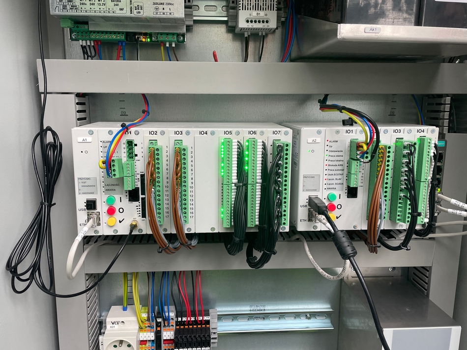
The aim of the project in the municipality of Dąbrowa Chełmińska, within the Bydgoszcz Distribution Area, was to build a smart grid, modernise it and upgrade the power supply. Existing pole-mounted substations were retrofitted with microBEL SRS controllers, whilst the newly built containerised substation was equipped with automation based on the microBEL SX controller. The microBEL SX device acts as a short-circuit current indicator, performing measurements and controlling the MV lines. At the heart of the substation is the microBEL ARN controller, which, by measuring the voltage from the LV busbars and the voltage at the LV line feeders using remote microBEL SENS controllers, together with the ECOTAP VPD change-over switch I-0-II from Reinhausen, is able to regulate the voltage via the transformer taps. Regulation takes place depending on the load on the LV lines from consumers.
The microBEL ARN algorithm first regulates the voltage on the LV switchgear busbars at the transformer substation so that the average value, calculated on the basis of the voltages from the individual phases, corresponds to the setpoint. At this stage, voltages from sensors installed deep within the network are not taken into account.
The microBEL SX device
Once the medium voltage on the busbars is within the set limits, the next step is to check whether the voltages in the individual phases are within the specified range. If it is found that the voltage in any phase is outside the permitted range, the algorithm calculates whether changing the position of the change-over switch I-0-II to eliminate this discrepancy will cause the permitted voltage range to be exceeded in the other phases.
If the algorithm’s assessment indicates that, following a change in the change-over switch I-0-II’s position, the voltage values will fall within the expected range, a control signal is then issued to change the change-over switch I-0-II’s position. At this stage, voltages from sensors installed deep within the network are not taken into account. If the phase voltages on the busbars fall within the specified limits, the next step is to check whether the average phase voltages measured by sensors deep within the network fall within the specified range.
If the medium voltage of any of the sensors does not meet this condition, an assessment is made as to whether the corresponding change in the position of the change-over switch I-0-II, which corrects the voltage deviation to the set value, will cause the permitted phase voltages on the busbars and the medium voltages of other sensors to be exceeded. If the above condition can be met, the control action is executed.
The algorithm includes under-voltage and over-voltage interlocks that monitor phase voltages at all measurement points, i.e. both phase voltages on the LV switchgear busbars and phase voltages from remote measurement sensors (microBEL_SENS). Voltage asymmetry is checked on the LV switchgear busbars, defined as the greatest deviation of the phase voltage from the average value.
The above describes the first part of a pilot project under the Infrastructure and Environment Operational Programme 2014–2020; Measure 1.4: “Development and implementation of smart distribution systems operating at low voltage and medium voltage levels, from the Cohesion Fund, 2014–2020”.
The experience gained by the Apator Group during the implementation described above will be applied to further projects concerning the implementation and development of innovative solutions, including during the construction of smart electricity grids, taking into account the rapidly developing Renewable Energy Sources.